HAPPY NEW YEAR!
2010!. Better get moving on this thing.
January Projects
The last three days have been dedicated to organizing my shop for the new year. Aways feels better to work in a clean and organized space.
Varnishing
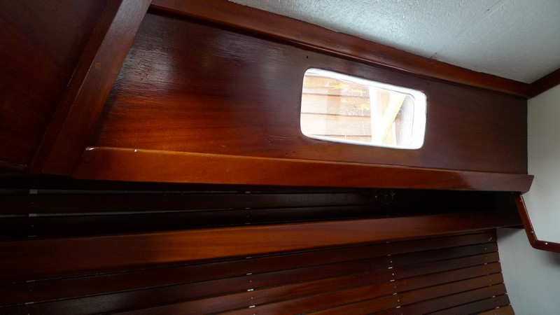
I have been putting final touches on some interior woodwork before installation. I am using Old Masters semi gloss spar varnish and it seems to look pretty good and matches the original finish well. FYI: Hallberg Rassy used a epoxy finish on all the interior woodwork. You have to clean well with solvents to get all the wax and other stuff previous owners have put on it and then sand it up so the new finish can get a bite. I have been sanding with 150 grit and I give it a quick once over(1-12-2010).

Shelves ready to be installed.(above)
Here is exterior woodwork getting varnish. I used Flagship on the exterior wood.(above)

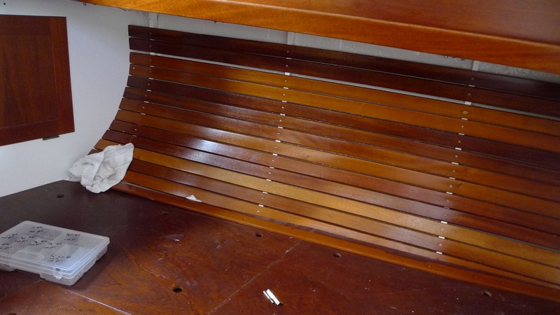
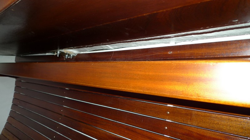
This is a picture of the forward berth. I am beginning to reinstall the mahogany slats. Also started the new electrical system. I am placing a bus under the slats to handle two leads to the navigation lights on the bow. The old bus was in the chain locker and corroded badly from the saltwater. This location will be better protected. I attached the bus with white polyurathane caulk and glued it to the hull. (above)
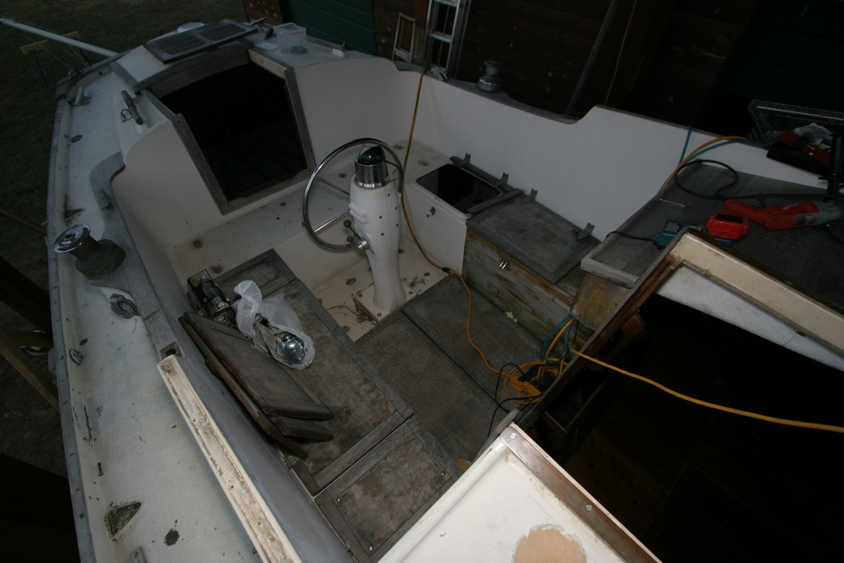
Assembling Cockpit(1-15-2010)
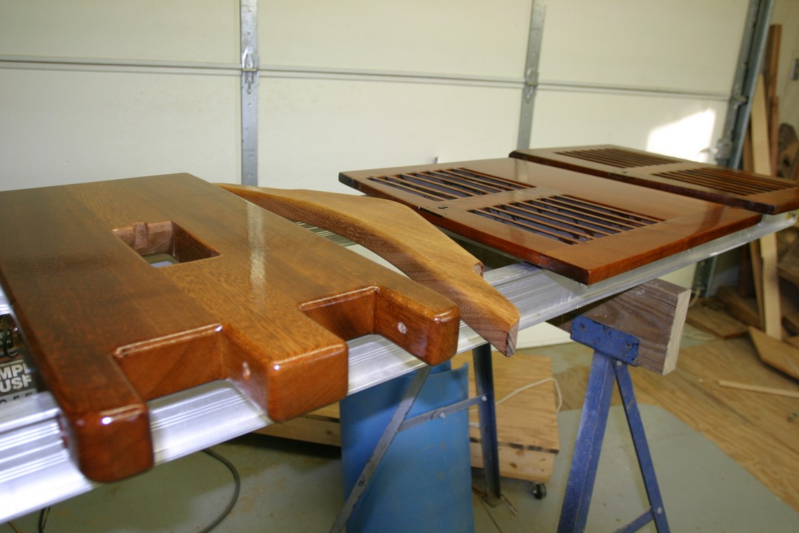
Putting main sliding cockpit hatch together(above and below).
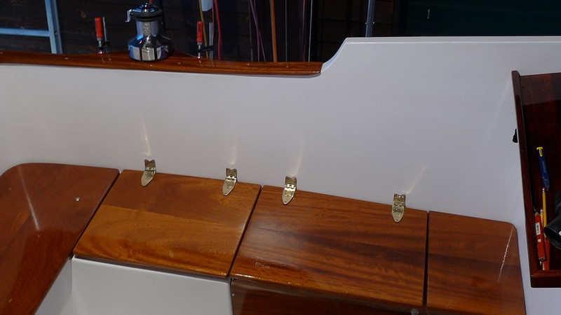
Using SS carriage bolts to bolt down teak seat boards. I placed 3/4 inch thick spacers under boards to allow for air flow.
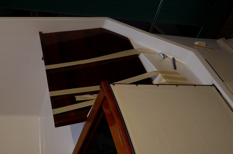
Used 3M 5200 polyurathane caulk to glue dashboard. I used 1/4 inch thick teak slats to lift board off the hull to allow for air space under so it can dry out from spray. That is how it was done at the factory.

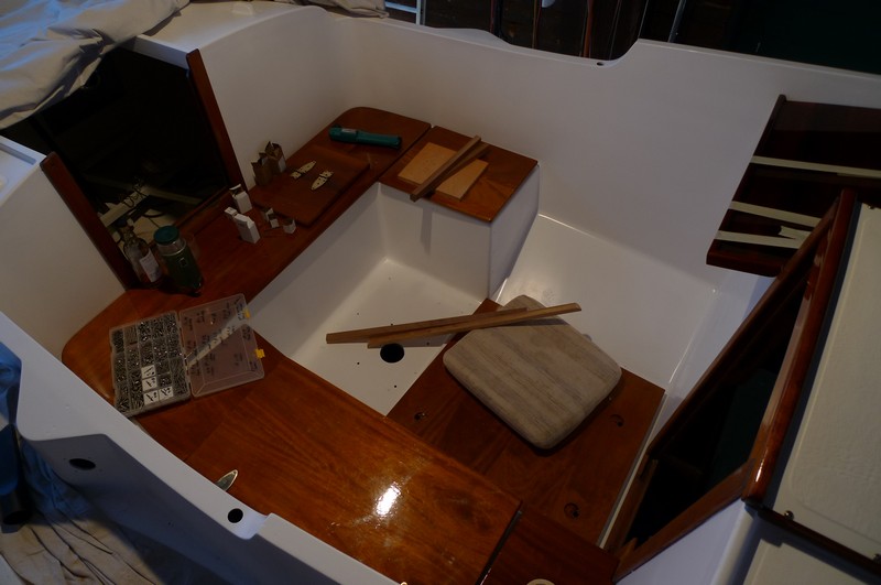
Finished wiring for bow nav. lights. Installed most of the forward berth mahogany slats. Worked on installing SS icebox in cockpit. Will hopefully have the cockpit reassembled this week. Will see.
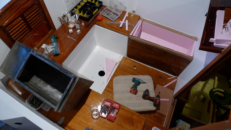
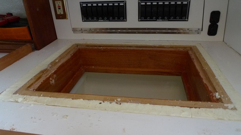
I have the pink styrofoam in place getting ready to install SS icebox in cockpit.(above)
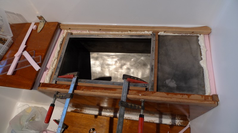
SS icechest is in place and I have used expanding foam to secure it in place and fill gaps.(above)


Mounted coaming trim and Lewmar #40 SS winch.(above)

Added 3/8 inch thick ply top to SS icechest. Ready for beer, people! (above/below)
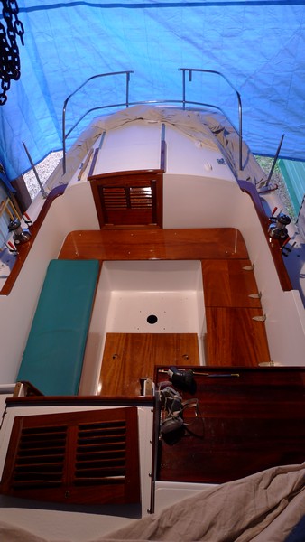
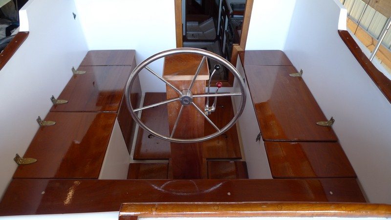
Overall look at cockpit at this stage in the restoration. (above)
Electrical System

The main electrical diagram for the Rasmus. (above)
Hull and Fuel Tank Damage
I knew before purchase that there was a problem with the hull. There was a wet look to an area at the bottom of the keel. It turns out the boat was probably dropped at one point, by a wave or during transport. The impact pushed the keel bottom upward cracking the concrete filler and pushing the filler up into the FRP fuel tank and separating it from the side of the hull. The impact also separated a fuel baffel from the hull side (which is also the tank side).
.jpg)
Diagram of damage to hull and fuel tank. (above) I plan to cut out two baffles and laminate a new tank section out of epoxy and fiberglass. The inside of the tank is fairly clean and looks like it will give a nice surface for the new laminate to grip. I will grind with 36 grit snadpapter to give it an even better grip and then apply 4 or 5 layers of fiberglass.
1/28/2010 Continuing the electrical work. Pulled wire for galley lights, head lights, forward berth fan, and mast lights. The Rasmus has plywood and FRP chases running down both sides of the boat which makes a great place to pull wires through. Mounted Xantrex battery charger. Cut the ply panels that will be mounted over the refrigerator that will hold the electrical dc panels. The elec. panels will be mounted on a hinged door for easy access.
Engine and Propeller Sizing
After reading Nigel Calder's Engine and Propeller section in Chapter Five of his book Nigel Calder's Cruising Handbook, I plugged in his math into a Microsoft XL spreadsheet to determine engine and propeller sizing. Below is the spreadsheet with the Hallberg Rassy Rasmus specs plugged in. Use at your own risk.
.JPG)
The shaft HP is what is needed to drive the boat at hull speed. However, there are losses of power in the system that need to be adjusted for such as alternators, engine driven refrigeration, and mechanical losses. Nigel divides the shaft hp number, in this case 31.89 hp by .95 and then adds around 3 hp for every alternator added of 100 amps. So if you plan to add a 100 amp alternator the horse power needed to drive the Rasmus rises from 31.89 hp to 37 hp including mech. losses. Without the 100 amp aternator you would need a 34 hp eninge. Looking at these calculations the minimum hp to drive the Rasmus is a 34 hp engine. I have read of Rasmus owners being very happy with 30 hp engine in their boats. Also have heard of owners being happy with their new 43 hp engines in them. In propeller sizing, I have plugged in the specs for a Westerbeke 35D engine with a 2.47/1 reduction gear. This is the engine I am seriously considering along with the Beta Marine 38. The Rasmus has an aperature of 22 inches for the propeller to spin within and it is recommended to have a 10 to 15 percent clearance between tips of propeller blades and boat. Using a 10 percent clearance factor, the maximum propeller diameter is 17.6 inches. Hull speed and shaft rotation in rpm determine propeller pitch and shaft hp determines propeller diameter. You can change engine size in hp, transmission gearing, and engine rpm's to adjust for propeller diameter and pitch. With a 31 hp engine rated at 3000 rpm with a 2.47/1 reduction gear, the recommended propeller diameter is 17.31 inches with a 13.58 pitch.Click here for pdf file on engine and propeller fit
Mounting the Brains
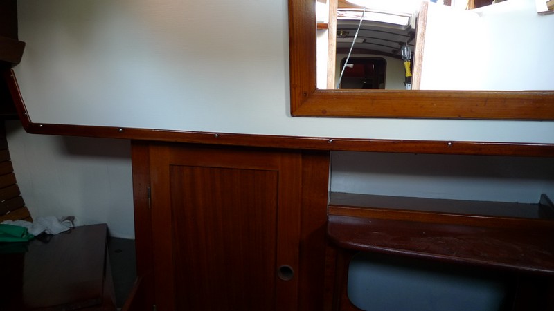
2-18-2010 Today I have installed the "brains" of the Rasmus, two Paneltronics fuse boxes. I used fuses knowing there is less to go wrong with them than with breakers. I placed them over what used to be the navigation station, but is now the refrigerator. The nav. station was a bit too small for me anyway and I will have to provide for navigation somewhere else. I glued a plywood panel on the hull of the boat behind the Paneltronic fuse boxes. I will screw electrical buses and whatever else I need to this. Below are pictures of the days work.

Painting the plywood panel where I will screw on electrical buses

Hinged door drops down so I can service the electrical system

Door in closed postion showing the front to the Paneltronics electrical boxes

New flourescent lights over sink, stove, and refrigerator. The ceiling panels were originally nailed to the cabin side trim. I opted to screw them back in place to I could more easily service any electrical problems behind them.
More Electrical
I have read and reread Nigel Calder's book "Boatowners Mechanical and Electrical Manual" and have to the best of my abilities laid out an electrical plan for the Rasmus to Nigel's recommendations. I would be amazed if there weren't errors in the system I drew up, but I am sure I will find them out as I go. Below is the "guts" of the system. I hope to get enough courage up to cut the 2/0 battery cable (at $6.00/ft.) with fingers crossed and get on with it this week. Below are diagrams.Click here for lastest electrical schematic
.jpg)
Electrical diagram laid over an image of the Rasmus
.jpg)
Diagram without boat image (above)
Here is a PDF of the new 12V circuits for the Rasmus 12V circuits
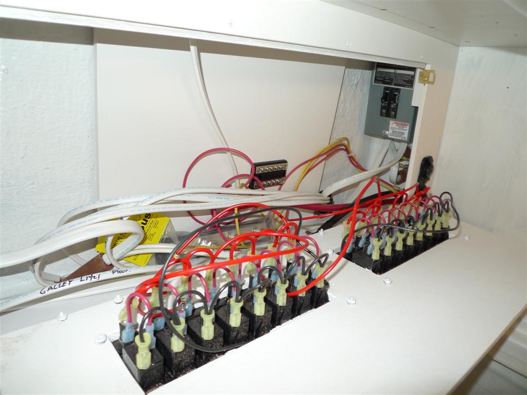
There is a bundle of existing wires coming out of the cabin side within the starboard cockpit locker. Below you can see I have cut them and attached them to a new bus(well, all but two, no idea what these go to). The wires go to the ceiling lites in the hallway in front of the head and main cabin, lites above stove, and mast lites that are bussed at the head entry.

In above photo you can see existing wiring for ceiling lights in main cabin and mast lights. The photo is taken in the starboard cockpit locker. The ceiling lights in main and aft cabin were the only wires I was unable to rewire do to their location.

Photo taken in starboard cockpit locker showing wiring for shore power, aft cabin ceiling light, aft cabin fans and added lighting, and stearn navigation lighting (above).
.JPG)
Photo taken in port cockpit locker showing wiring for mast lights, added head locker lights, new main cabin flourescent lighting, and forward berth reading light and fan (above).

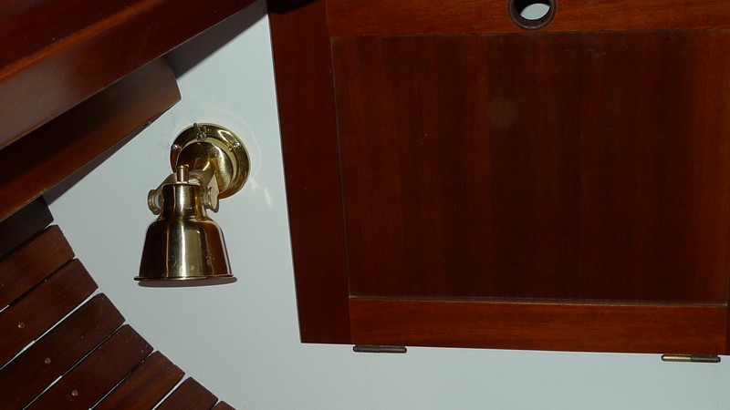
I rewired to the mast lights do to bad corrosion on the existing wire. I placed a switch on the mid mast light so I could turn it off and leave the mast head light on in case the glare off the deck was a problem. I had to cut a wooden chase for the new wiring and screw to the head aft bulkhead (above).

New Zantrex battery charger placed under main cabin settee (above).
Bang for the buck
I have been curious in the relationship between PHRF and a given amount of sail area. I have been impressed with what I thought was good PHRF (186) given to the HR Rasmus with it's small sail area of 485 feet. So, I thought I would do a little more research into this and just see how the Rasmus stacks up with other boats its approximate length. I took 32 sailboats that are recognized as good cruisers with a few racers thrown in. I took the average of their PHRF ratings and divided their own PHRF rating with this average. I then divided that ratio by the sail area. It looks to give a pretty good indication of the relationship between PHRF and sail area among the boats sampled. Don't know if the math is completely sound, but the order looks to be reasonable. The HR Rasmus has the smallest sail plan in the group at 485 ft^2. And the PHRF is at the lower end of the group at 186. But the Rasmus jumps to the upper end of the list when considering sail area/average PHRF/PHRF. The list does give a comparison on how much speed the boat may have with the amount of sail a sailor may want to wrestle with. Any ideas?Click here for pdf file on sail area to PHRF comparison
.jpg)
Above is a list of 32 sailboats that are sorted according to their sail area divided by their average PHRF divided by their own PHRF. Included is motion comfort and hull speed. The larger the number under motion comfort the more comfortable the motion.
.jpg)
Above is two lists, one sorted according to their sail area and the other sorted according to thier speed rating. Boat Ratios Page
Below is new Marinco Power inlet

Plumbing
First let me say this, I HATE PLUMBING! My goal is to get through this quickly and painlessly but I know it won't happen. My first to do was to make a preliminary list of the plumbing features in the boat. And here they are.Plumbing specifications The boat is stripped of all plumbing, and everything else for that matter, and I will be starting from scratch. More about plumbing later.
More electrical
(3-1-2010)Well, I turned 51 today. Life is good! And warmer weather is on the way, thank goodness. It has been a colder than normal winter in Arkansas this year. I wired the 120AC breaker box, ran #10 wire to battery charger and wired it, ran #1 wire from battery box to DC distribution panel, wired two AC outlets, wired two DC lighter sockets, and set up bus bars and preliminary wiring for batteries. I decided to go with two AGM Lifeline 4D batteries that will give me a combined power output of 420Amp/hrs. I am going to wire them as two battery banks and see if 210Amp/hrs is enough to power the boat and use the other as a starter battery. If that does not work out, I will combine the two 4D batteries for the house bank and add a battery for starting. I have wired it so the possible conversion will be easy. Below are pictures of the work.
Most of the wires are pulled to the distribution box. I am waiting on the mailman to bring a bus bar to finish this up

I have started the wiring layout at the battery charger and battery banks. I am waiting on my battery box to dry to finish this up(I made one out of 1/2" plywood and epoxy).

I added a 120V AC outlet and two 12V lighter plugs on front of the panel.

An overall look at the work at this stage (above and below).

Removed all seacocks and thru hulls
With the right tool, I was able to remove all Groco SV series seacocks(6) and thru hulls in about an hour with the help of another. They all came out too easy in my opinion and I was glad I decided to replace them. I was reluctant to replace because I think the old Groco SV series design is fool proof. These older seacocks have the rubber cylinder that you compress with a pressure plate that sealed the thru hull. Nothing to corrode. I will replace with the Groco BV series of seacocks and use a 1/2 inch G10 fiberglass backing plate instead of plywood.
Hull Erosion and Pitting
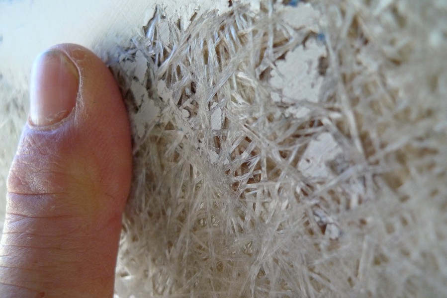
I was asked how my HR Rasmus's 34 year old hull looks under the gellcoat. Below are a few pictures of what I think you could expect from a 34 year old hull that has been neglected.
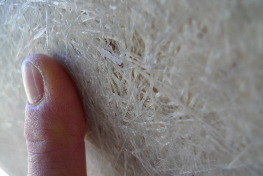
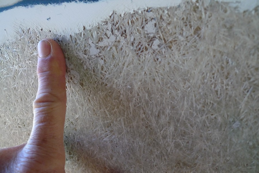
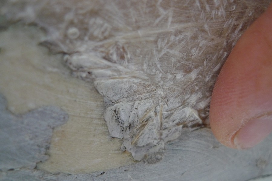
The pictures above were taken close to the waterline. This is the worst of it.
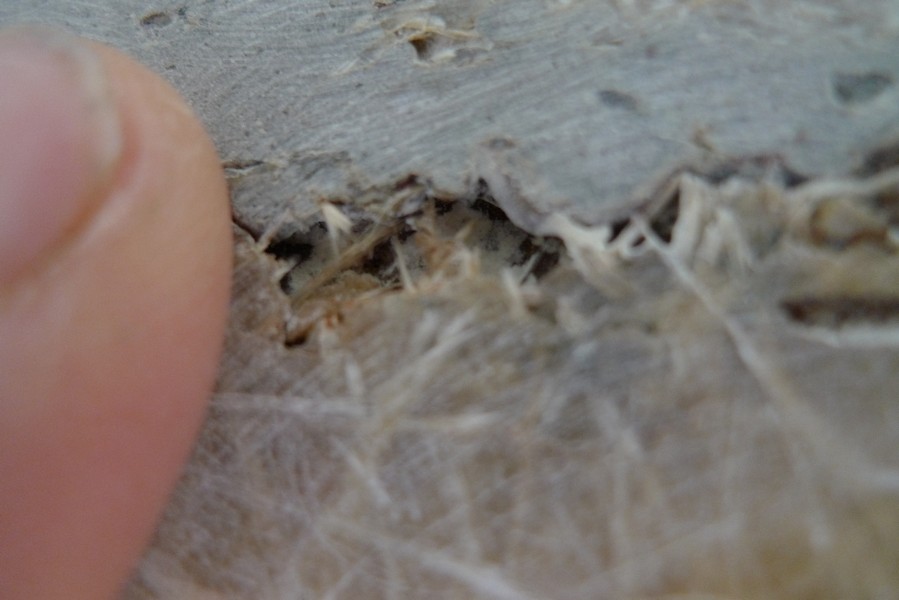
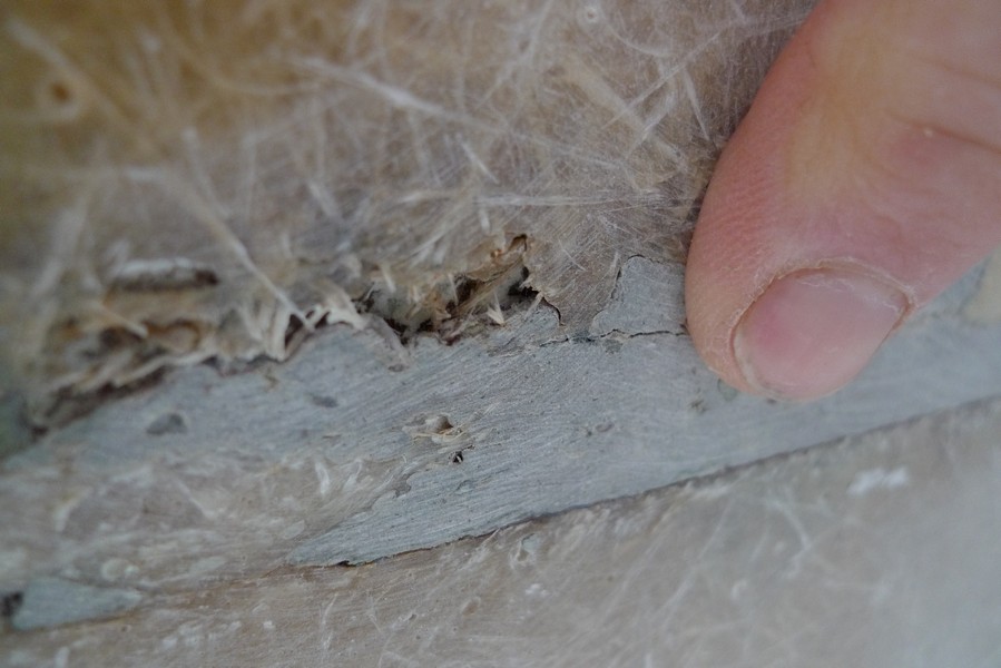
The pictures above were taken along the centerline at the bottom of the keel. The boat was built in halves and laminated together. There is a groove running the length of the boat along this centerline. It was originally patched with epoxy putty. Over time some of this putty has chipped out and eroded. There is hull erossion along this centerline in places. Above are pictures of the worst areas of this erossion on my boat.
Keel Damage
Below are pictures of the keel damage from an impact. I have cut out the bad laminate and will grind out more to make a tapered edge for the new laminate to grab. The brown stain is diesel fuel stains from deisel leaking thru the cracked tank and hull.
Porthole replacement
I have started replacing portholes using 3/8 inch polycarbonate sheets. They were easy to cut and drill for installation. The four I have already replaced went on nice and easy. I am using 3M 4200 UV as a sealant. I may use 3M marine silicone on the others because I ran out of 4200 UV and just to see which works better.

Electrical test
Hooked up a battery and turned on the power with fingers crossed and nose on alert. I sensed no wires frying and no breakers popping so all is well.


A look at the fully wired electrical panel.
Is the Hull dry after 2+ years on the hard?
I duct taped some clear plastic to the hull in spots to check for hull moisture. I read that if you don't see any moisture between the hull and plastic after a few days, you can expect to have a dry hull. Well, there was not a trace of moisture after a week. So far it looks like this hull has dried out pretty good.

Plumbing, have I mentioned I HATE plumbing
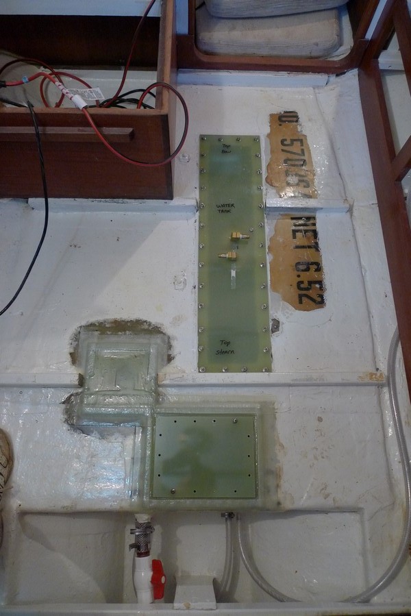
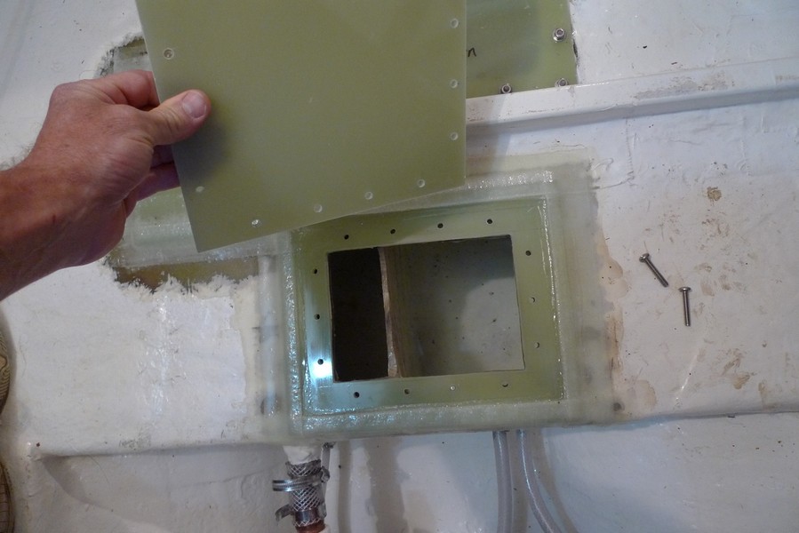
I made a new water tank lid out of G10 fiberglass and got it installed. The brass fittings are the air vents. I also removed the ss receptacle that the galley table support nested in. It protruded in the water tank. I am going to do away with that extenion system so I just fiberglassed over the round hole. I also added a viewing port on the aft end of the water tank. I placed this port on the low point of the water tank will allow me to get all the water and dirt out when the tank is not in use and to also inspect the outlet lines for any clogging.
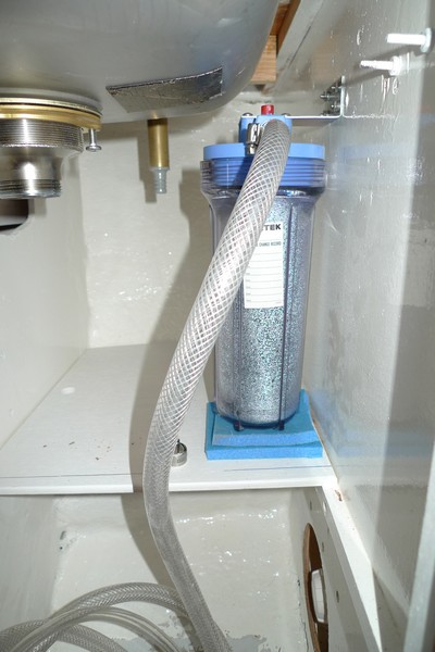
I added a water filter and placed it beside the galley sink.
Engineless?
I keep trying to convince myself to go engineless with this motorsailer. Crazy huh? And now I see all the millions of gallons of oil polluting our beautiful gulf coast, it really gets me motivated to make it work, that is, without an engine. The BP spill will reach the Gulf Coast National Seashore's barrier islands, a place that I have explored in my wooden dory. It is a magical place that I have grown to love. My first trip out to the islands, Darryl and I left out of the Hard Rock Casino boat launch in Biloxi headed for East Ship Island. The wind was blowing hard. I was tempted to abort the trip. A local walked up looking at our unusual boat and asked where we were headed. We told him we were headed to Ship Island. He said, "in that, today, your going to die". Well we didn't but it literally scared the pee out of me. We motored thru 4-6 foot chop for 4 hours with our trusty nissan 5 hp motor. We had to bail out the boat several times along the way. We didn't see another boat that day, just us and the bay. When we reached East Ship Island, it felt special. We were on this very small, desolate spit of land. Just us. It was raw and beautiful and I felt we had accomplished something that day. And man was I glad to be standing on land after that exciting ride. I am glad I exlored those isands. Who knows their fate at this point. Gulf Shore Barrier Islands
Hull Work
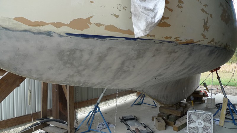
5/17/2010 I finally decided to strip the gelcoat. I can work about 3 hours before my arm gives out. I am using 24 grit disc on my Festool rotary sander. I can use a high speed 4 inch disc sander with 40 grit to quickly take down the gelcoat on the flat surfaces only. It will gouge the hull on any of the curved surfaces. The Festool is easier to control with its variable speed and works ok on curved areas. I still have to be very careful and move the tool constantly to keep from gouging. The hull is eroded most at the waterline and the turn of the bilge. I am stopping most other boat work until the hull is stripped and the area cleaned of fiberglass powder.
The pictures below show the results of 7 hours of grinding as described above.


The condition of the laminate varies greatly depending on location. The areas in the worst condition were at the waterline and at the concave bend just above the keel. The laminate was in best condition on the flat areas of the keel. Any ideas on why there is a variation? Below are pics of these areas.

Flat surface on keel side

Waterline

Concave bend above keel
Seacocks/Thruhulls/Backing Plates
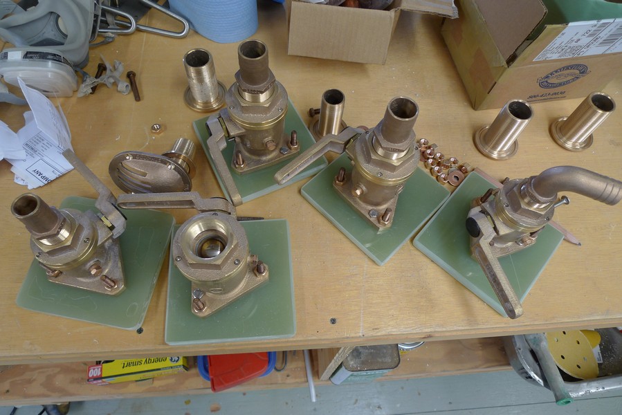
I have been working on the installation of new seacocks/thruhulls. I have milled some 1/2 inch thick G10 FRP for backing plates for the new seacocks. I have drilled 1/4 inch deep x 5/8 inch diameter holes with forstner bits to accept 5/16 inch silicon bronze bolts that will be epoxied into place to accept the seacock. I will bolt the seacock to the backing plate. I will use epoxy putty to seat the backing plate/seacock onto the hull prior to fiberglassing the backing plate to the hull with fiberglass tape. Pics below.
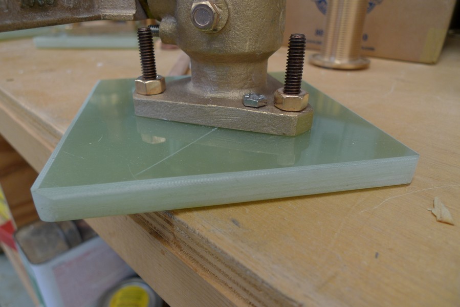
Used silicon bronze bolts to bolt backing plate to seacock.
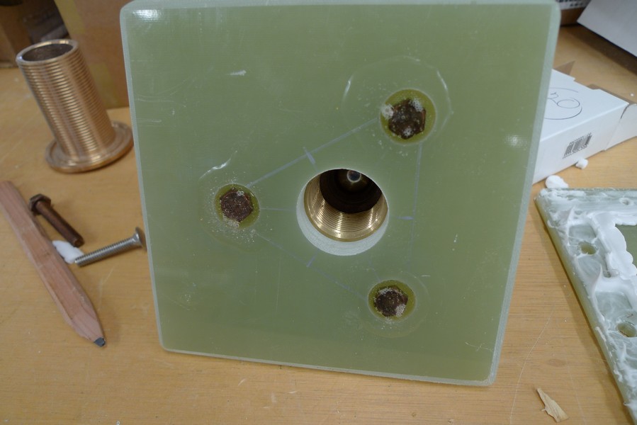
The holes lined up on first try. That's a change. Bolts are countersunk and epoxied in place.
5-13-2010 More gelcoat removal today. Worked about 2 hours grinding. That makes a total of nine hours so far. Started using a belt sander to remove gelcoat along the concave bent above the keel. Seems to be working well with fewer gouges along this tough area.
Bulkhead/Compression post in relation to Mast Step
I was asked about the location of the Bulkhead/Compression Post in relation to the mast step. I placed tape on the cabin top where the bulkhead and post lay. You can see the six bolt holes where the mast step bolts down on the cabin top. I looked at pics of an older Rasmus and noticed that the "landings" are different sizes. It looks like on the later models they extended the landing to reach from the two bulkheads forming the head area in order to strengthen the mast support. I wonder if Hallberg Rassy had problems with deflection on the earlier model Rasmus. Anyone know?
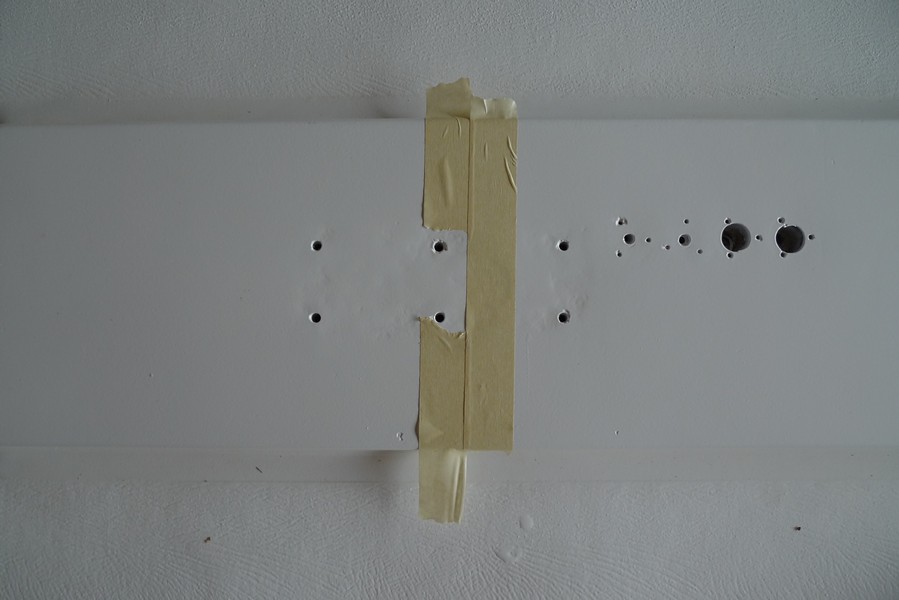
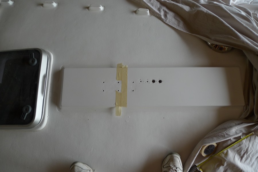
Pics above are the mast step "landing" area of a 1974 HR Rasmus hull #337. The tape is the location of bulkhead/compression post.
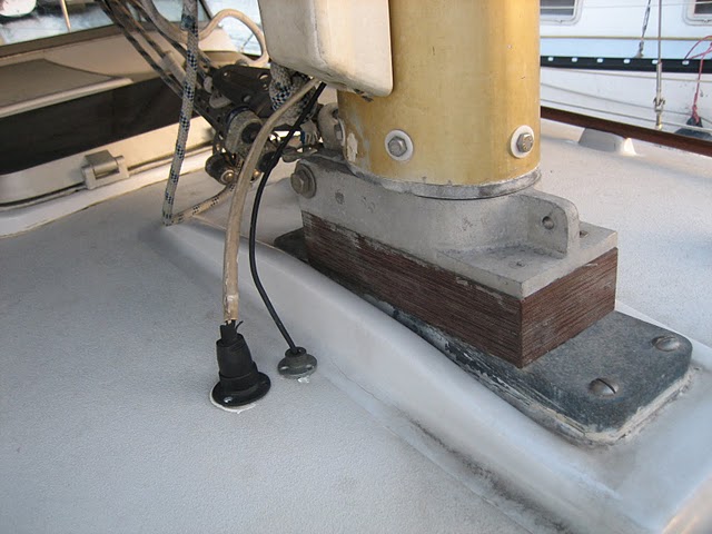
Pic above is the mast step of a 1972 HR Nab/Rasmus hull #100.
More sanding
Put in another 1.5 hours sanding off the gelcoat. My technique and speed are improving. I have started using my 4 inch high speed grinder with 36 grit. I had previously stated that this is too aggressive to safely remove the gelcoat, but my technique is improving and patience declining. I am able to take most of the gelcoat off with the grinder and will finish up with the Festool variable speed rotary sander. It is much faster with the grinder but you must be VERY careful or you will gouge the hull.

One more Portlight in place
Installed another portlight, this time using butyl tape I have been reading about. One thing I know, it will be much easier to replace the glass using butyl tape. I squeezed out a lot of butyl and it cleaned right up with no problem. I will have to thru bolt some of the fasteners but I have planned for that with the purchase of some nice acorn nuts. Anyone use butyl tape for portlight installation?

Portlight installation using butyl tape.
The Best Pizza
I have been learning Jeff Varasano's pizza tricks the last couple of years. If you love pizza, because this takes a bit of work, try out his recipe. Don't expect to get it right the first time, but with practice, you will make the best pizza you have ever eaten. Here is his link: Jeff Varasano's Famous New York Pizza Recipe Below is a pizza I made today that turned out really nice. YUM!

One of Pat's best, well, really Jeff's.
Keeping up with a few adventures
I have been keeping track of a few adventures out there on the high seas. One is Jessica Watson. A very large CONGRATS goes out to Jessica Watson, yougest to sail around the world. And please, no arguments on whether she "really" sailed around the world, really. Way to go Jessica! Jesica Watson's Page Another is Nick Jaffe Nick's Page, another Australian who sailed from England to Australia in a 26 foot Contessa, a boat I seriously considered buying. I found out about Nick while attempting to boat across Yellowstone Lake last year in October. The park ranger told me not to take my dory out in the middle of the lake, but to hug the shore. He said mountain storms are deadly and the water is 39 degrees F. If you go in you have about 20 minutes. So what do I do, I go right down the middle of the lake, because heck, I've taken this boat 12 miles offshore. Well, Yellowstone Lake isn't the warm waters of the gulf. This lake is meaner. The wind picks up, its big waves and whitecaps, I am soaking wet and shivering uncontrollably, and my motor starts to choke out. We just make it to the nearest shore to start a fire before I go into full blown hypothermia (been there, done that, but that's another story.) Next morning the motor won't start, so it's a 10 mile paddle back to the north shore and then another 10 by road to the car. We take care of that business and then set camp near Lewis Lake, and there camped next to us is Nick Jaffe's brother RyanRyan's Page. Ryan tells me about his brother Nick and we share some great hikes, scotch, and food together for the next couple of days.Yellowstone Images
Continue to Remove Gelcoat: Best Sanding Technique So Far
5-19-2010 I put in three more hours of sanding on the gelcoat. My patience continues to wear thin, so I tried another technique that is the best so far. Here it is: I start with a high speed 4 inch grinder with 24 grit 4 inch disc. I make nice, fluid sweeping motion going high to low and let the sander travel about 16 inches before a raise it off the hull. I only let the top third of the disc touch the hull. In other words, the sander is tilted at an angle of about 20 degrees. I start this motion using light pressure but quickly increase the pressure while I observe the results as I go. What I am trying to achieve is a nice uniform groove in the gelcoat that just leaves a paper tissue thin thickness of gelcoat left on the hull. I can actually see the laminate through the gelcoat when I finish this stroke. I repeat this stroke right next to the one I just finished and continue down the hull, always starting high and finishing low. Sometimes I have to go over an area twice to get the right depth. This leaves a grooved hull(but only in the gelcoat if done properly), but I take care of it by changing the grit from 24 to 36. I go back and start removing the rest of the gelcoat by placing the disc flat on the hull and letting the rotation of the disc oscillate the sander head in small circles, just like an orbital sander would do. This takes a bit of practice but works great once you get the hang of it. I have found that this technique done right, leaves very few grooves in the hull and is extremely efficient. If you want less aggressive removal use a 6 inch random orbital sander with 36 grit discs instead of the 4 inch high speed grinder with 36 grit disc for the final gelcoat removal.
5-20-2010 Three More Hours of Sanding
I now have about 19 hours total on gelcoat removal. If I knew at the start what I know now I think that could be cut in half. Below are pics of the progess.

Port side almost finished. The gouges on the topsides is old damage that was patched with bondo. I will repatch with epoxy putty.

This is a picture of the gelcoat after going over with 4 inch 24 grit disc. It is rough and grooved but the laminate is just exposed with little grooving.

This is a picture of hull after going over with 24 grit disc and then using a 6 inch 36 grit disc on my Bosch random orbital sander to finish it out. This leaves a very fair surface.

Starboard side almost complete.

Another port side shot.

Another starboard side shot

Rudder hardware showing the blue/black fairing putty used. It was brittle and cracking in spots so I ground out the bad and will replace with new putty.
Gelcoat Removal: Final Analysis
Ok, I have finished removing the gelcoat. I have tried several different methods using various tools and now I can comment on what worked best in removing the gelcoat. The tools needed are a 4 inch angle grinder (I like the Makita ) with a sanding pad and 24 grit sanding discs and a Bosch 6 inch Random orbit sander model 1250DEVS with 36 grit sanding disc. This Bosch sander has been the most used tool throughout this boat project. This sander has a switch that lets you choose between aggressive sanding and less aggressive sanding. I can't say enough good things about it. You also need a 3M full face mask respirator, a spray painters cotten hood, and some tyvek suits and long sleeve gloves. Start with the grinder with 24 grit paper and take off all but a very thin layer of gelcoat as described above in the 5-19-2010 entry. Then switch to the Bosch sander with a 6 inch 36 grit sanding disc and put it on the aggressive setting. Sand 4 foot area at a time and move the sander continuously. Here is the trick: When the hull was laid they sprayed a thickness of gelcoat on the mold prior to laminating. On my boat, the layer of gelcoat is not consistent in thickness, so if you follow the contour of the gelcoat with your sanding, you will come out with an unfair hull. Let the sander take off what it needs to get a fair hull. This will leave some small blotches of gelcoat on the hull. This will actually help in the long run and is like a thin fairing that you can leave on the hull. I have found that blistered and pourous gelcoat will show up and chip off during the first sanding with the 24 grit. What is left after this first sanding is usually good, well bonded gelcoat. I have found that this produces a very fair hull after sanding. The photo below shows the results after using the above method. Notice the small blotches of gelcoat left on the hull. In some areas even more gelcoat is left on the hull.
Injured!
I was delt my first painful injury while working on this project. I was moving my 300 pounds of 3/8 inch anchor chain from my garage to my shop in a wheel barrow. Between the house and the shop there is a creek with a footbridge over it. There are ramps on each end of the foot bridge. As I pushed the wheel barrow up the first ramp, I didn't quite make the top and was pushed back down. OK, I am going to have to run up the ramp, so I get a good running start and up I go. I have a hill to go up to get to the shop, so I decide to get a good running start while on the bridge. Away I go, across the bridge and down the ramp at a good clip. As my wheel barrow meets the ground, it digs in and comes to an immediate stop. I slam into the wheel barrow with 300 pounds of chain. My thigh slams the edge of the wheel barrow and the left handle augers into my left arm at the elbow joint. I hit so hard the wheel barrow goes end over end with me cartwheeling through the air with arms flailing. The wheel barrow and I slam to the ground upside down after turning a flip. The pain is so great there is no yell, gasp, or scream. Just a low moan that continues for several minutes. Bernard, my dachshund, comes over and licks my face. Bernard knows I am in pain. I lay there for 3 to 4 minutes before I sit up to assess the damage. I thought I had a broken left arm and leg, but after a minute more I decide its ok to get up and walk around a bit. I have some sweet bruises and a very sore body, but no more.

Bernard, my faithful companion
Toe rail refit
I had previously cut a teak plank up for the new toe rail. I had read that steaming teak for a bend was tough, but I had a plank with a bow in it and thought that would give me some help in bending. I cut the planks and steamed them. Then quickly clamped them in a form in the shape of the boat curve. They clamped in place OK without splitting, but when I released them they sprang back quite a bit. After assessing the teak I had, I determined I didn't have enough to finish and I sure didn't want to spend more money on teak and I thought the bend was going to really give me some trouble to do without splitting or other problems. I had some 2 inch thick cherry already and decided to use it and paint the toe rail instead of varnish. I had previously marked off the curve of the boat on 1/4 inch plywood and cut on the line to reproduce the shape. I set the plywood on the cherry planks and marked the curve on the cherry and then cut the planks out with a skill saw. I made sure I didn't incorporate any wood defect in the finished plank. I then used my bandsaw to cut the rough width of the toe rail. I then ran the rough shaped toe rail through my 15 inch wide belt sander edge wise and convex side up. This cleaned up the edge of the toe rail plank very nice. I then filled it 180 degrees on edge with concave side up and cleaned that side. This produced a nice toe rail plank with uniform width and smooth sanded edges. The pictures below show how I finished the toe rail up.

Here are the jigs used to rout the joint I will use to connect the toe rail. I gave the jigs the same curve as the boat and the same width as the toe rail. I cut them out of plywood first and then found that the ends are to flexible to support the router, so I made some more out of oak. The shape of the joint was determined by my edge sander drum. I could cut nice reproducable curves into my jig using this sander.

A toe rail plank clamped and ready to recieve the jig

The jig clamped in place and the router bit used to clean up the joint after rough sawn with a jigsaw.

Cleaning up the joint with a router.

The freshly milled toe rail dry fit in place. Notice I rounded the edges of the toe rail with a router.
One Step Forward, Two Steps Back
The Good. I finished cutting and dry fitting the cherry toe rail. I am going to leave it in place for a couple of days to see how the wood reacts to its new home. I was careful selecting the cherry from my wood pile but there is always a chance I missed a defect and it should show up fairly quickly in the Arkansas heat. I will apply 3 coats min. of epoxy, let dry for at least a week, sand smooth, apply a 2 coats of Interlux Primecoat, sand, and then paint a nice teak brown. I feel like this will have a good looking, long lasting, low maintenace finish. We shall see. Pics Below.


The Bad. I WAS preparing to paint the topsides and as I was removing some caulking with a scraper a large sheet of paint came off instead. After doing some investigation, I find the entire topside paint job has a weak bond between the 3rd and 4th coat. There are 6 coatings on the topsides. So, I scraped all the paint off down to the 3rd coat and will do some more reasearch on what to do next. It is a definate setback. Below are pics.


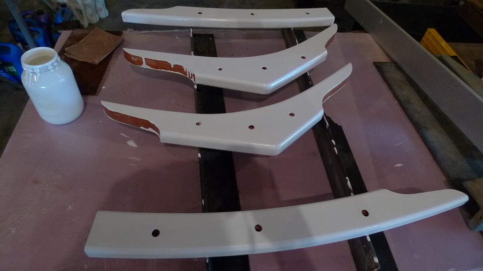
Epoxy Coating the Toerail
I applied 3 coats of epoxy with West Systems yellow foam roller. It was messy and I had to stay with it to catch the drips and runs and keep everything nice and smooth, but everything went on pretty easy. Only problem was the 100 degree heat. Sweat was running off of me and was a nusiance even with two fans blowing. Pic below:

Cherry toerails coated with epoxy. I will let dry for a week, wash off the amine blush, sand, and coat with Interlux Primekote, and then apply a single part urathane paint.
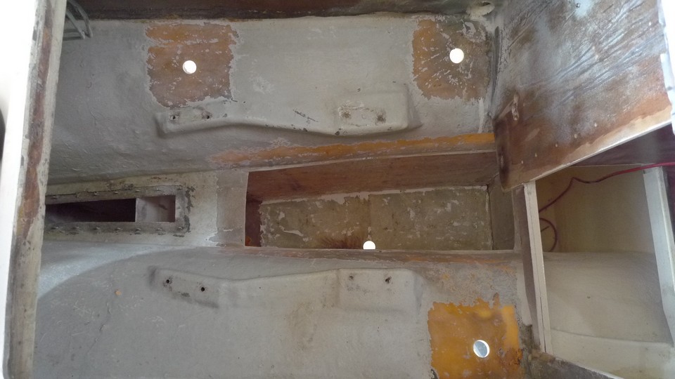
Fuel Tank Repair
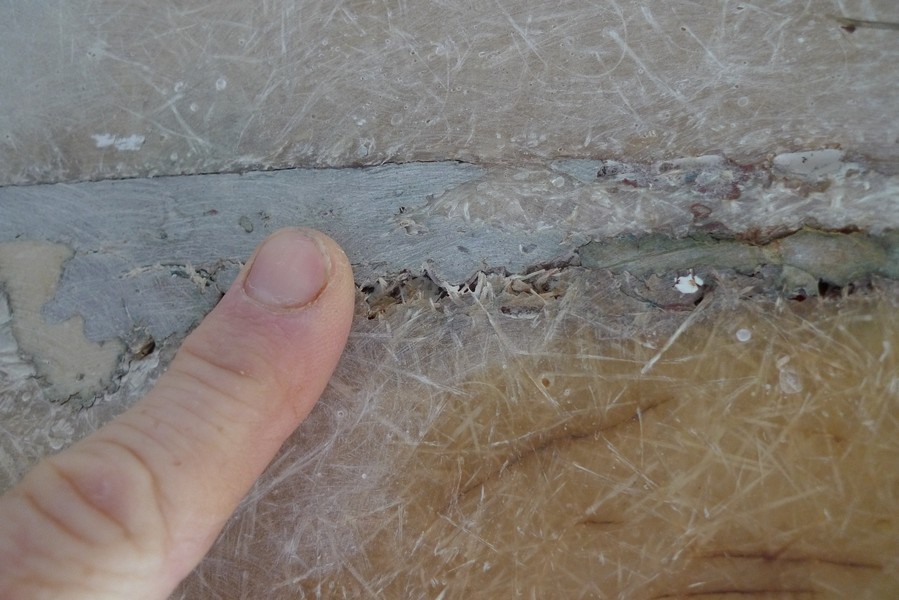
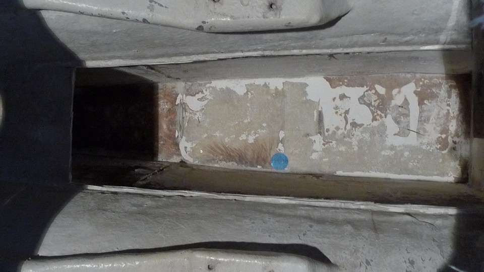
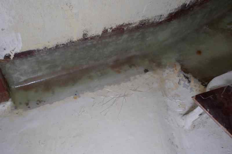
I spent about an hour grinding the inside of the fuel tank with 24 and 36 grit using a 4.5 inch disc sander. Very hot and dusty. Had my tyveck suit on and full face mask repirator for protection. My long sleeves pulled up a bit and I got a painful dose of fiberglass shards in my arm. It cleaned up pretty good and I think I will get a very good bond between the old and new fiberglass. I can clearly see the cracked fiberglass along the bottom of the tank. Pic below.
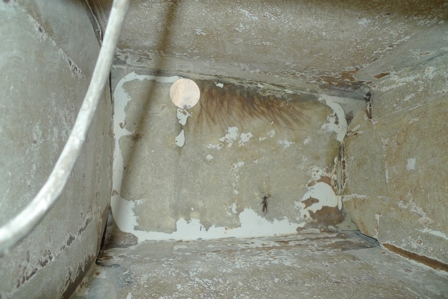
You can see the many cracks in the tank laminate. The fractures are darker from diesel seeping into the laminate.
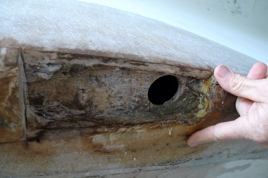
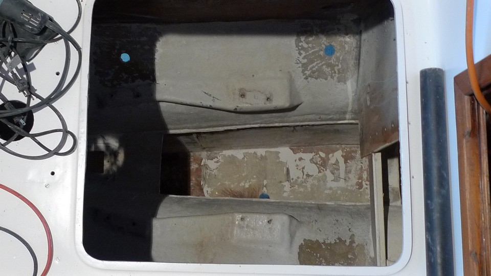
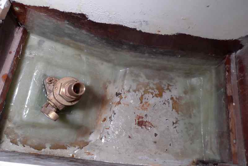
I previously thought the damage to the fuel tank was contained between two tank baffles in one compartment, but after a closer look, I realized that it goes into two more compartments. This really complicates things. Now I will cut the top off the fuel tank and cut out two baffles. This is probably the best way to solve this problem and I am happy I am doing it. Cutting the top off will give me more room to work, will allow me to see all the damage and fix the problem correclty. I used a 4 inch rotary grinder with a diamond blade attached. It took about 30 minutes. Pics below.
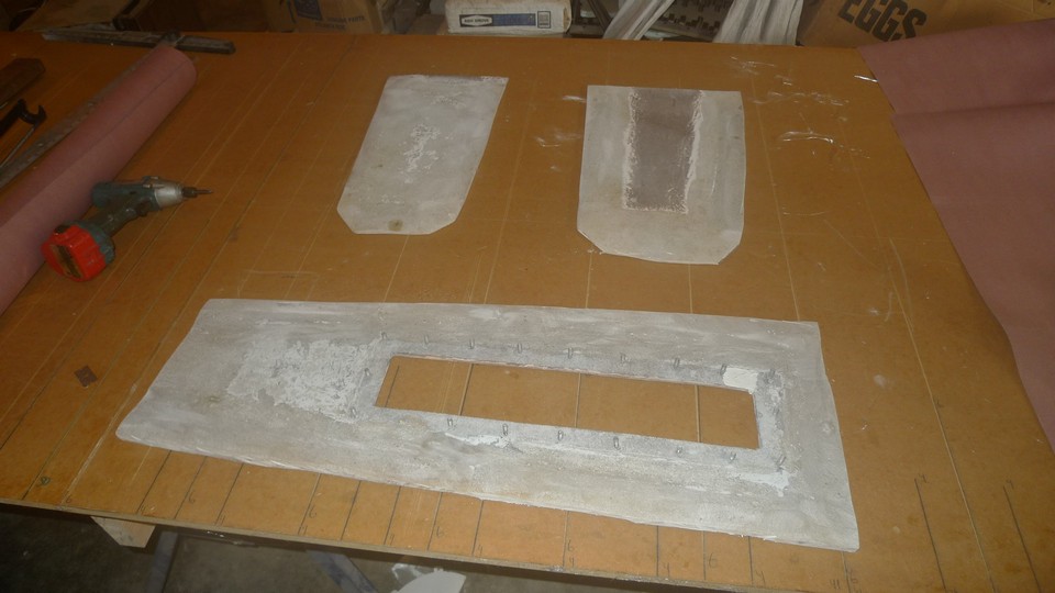
I finished grinding out most of the gelcoat inside the fuel tank. Looks like the gelcoat is a good barrier to diesel. I could see very little, if any, diesel absorption into the laminate underneath the gelcoat, except where the laminate was cracked. Then it looks like the diesel can run laterally through the laminate a saturate the laminate. I say this because where the laminate is cracked, there is a brown stain throughout the laminate. I am assuming this is from the diesel. Pics below of the prepped fuel tank and of the baffles and tank top that I cut out with a 4 inch grinder with a diamond blade.
Patching Holes and Barrier Coat
Why do I have holes in the hull? Well, I took out some thru hulls and seacocks that I will not replace. I decided on a composting toilet (going greener) and that will not need a thru hull. I also removed 2 old transducers. So, I have started patching holes with fiberglass and epoxy.

I did a small test area concerning the epoxy barrier coat. Pic above shows the work. I rolled on 4 coats of epoxy with no fillers or additives and used a plastic 6 inch wide putty knife to work the epoxy in the pits caused by hydrolysis. I had to keep working the putty knife until the epoxy set enough to not run. I did this on the first 4 coats. I then began adding West System barrier coat additive, which is a grey aluminum powder, and rolled on 3 more coats. I let this set and then faired with system three quickfair, let set, and sanded smooth. I then rolled on one more coat of epoxy and alum. powder.

Pic above shows three holes I patched using fiberglass and epoxy. Sanding will come later.
Getting Ready for Major Fiberglass Work
I set up a fiberglass cutting station next to the boat. I found that a 16 foot by 4 ft. table along with sheet rock squares and single edged razor blades works great for cutting sectins of fiberglass. Pics below.

Cardboard boxes to keep my cut fiberglass
.
Tools that work well for me: squares, straight edge, scissors, and single edge razor blades.

Table

Resin station
The Dingy
It seems lately that I have been taking more steps backward than forward. So, I must rejoice in the fact the the dingy has been completed! Yeah, I built it 6 years ago. Pic below
.
Doug Hylan design Maine Peapod, which will become my dingy(if I can figure out where to put it) was completed 6 years ago. It hangs patiently from my shop ceiling.
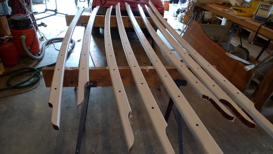
More Toerail Work
I have rolled on 3 coats of epoxy, sanded, and applied one coat of Interlux Primekote on the toerails. Next will come 2 coats of paint. Pics below.
Hull Repair Schedule
Here is the order I will attack the hull repair.
1. Laminate a patch inside fuel tank to plug the hole I cut.
2. Fill the void between fuel tank and bottom of keel with Marine Tex putty.
3. Laminate the damaged area of the keel and fair.
4. Fill the gouges on bottom of keel with thickned epoxy and fair.
5. Laminate a 1/2 thick new bottom to full length of keel.
6. Laminate a 1/4 inch new bottom to fuel tank and sides.
7. Roll on at least 2 coats of epoxy on hull filling voids as epoxy cures.
8. Apply fairing compound while epoxy is still uncured.
9. Sand hull fair when fairing compound has cured.
10. Roll on 3-6 coats of Interlux Interprotect 2000.
11. Sand any imperfections and let dry, then apply bottom paint.
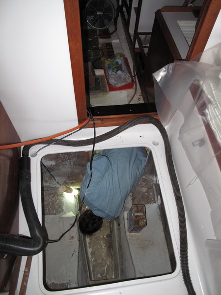
9/11/2010 Fuel Tank Repair
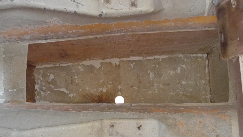
I had precut my fiberglass, organized the work area, called a friend, and was up and ready to work at 7 am. It took 11 hours of work to get the tank back in pretty good shape. I layed down 6 oz. glass along the bend on the bottom on both sides of the tank. Started with 1 inch tape and worked it up the 12 inch tape. That took 15 layers. Then I went to 18 oz roving and tried to lay 41x50 inch pieces. I quickly found that I couldn't lay it down nice, it was to large to handle, so I cut them down to 20x16 inch pieces and staggered. That worked much better. I put on about 6 layers on bottom and up the side half way. I lay 2 layers of roving the rest of the way to the top of the tank. I then placed the baffles back in place, placing them on a piece of foam to lift them up off the bottom 1/4 inch and placed a foam piece on each side to jam it in place. I then bonded the baffles in place using 6 inch wide tape. I used epoxy on all the lay up. The worst part was keeping the sweat from dripping in the work and the very uncomfortable position I was in for such a long period. Pics below.

Standing in the bilge, contorting my body thru the hatch and leaning over the fuel tank, I start the tank repair.
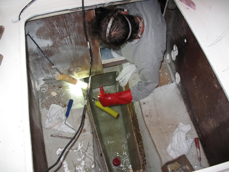
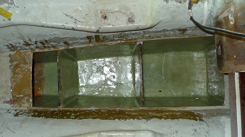
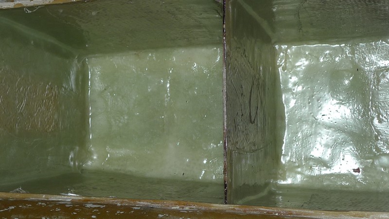
Final product with baffles taped in place. If this doesn't work, well I don't know what would. All I lack now is taping the top back on.
Finishing the Refrigerator Box
I designed the top and lid to the refrigerator and quickly cut and glued it together. I used African Mahogany. It is a bit heavy but it will have to do. I designed the lid to have two seals with an air space between. The lid will have 3.5 inches thickness of insulation (pink styrofoam). Pics Below:

This is the trim that will hold the lid. I have it glued in place with 5200 and sealed with expanding foam. I will cut the foam flush with the counter top and trim with Mahogany. It will look damn good, whether it works or not.
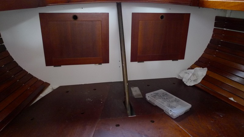
9/17/2010 Assembling Aft Cabin: I am starting to put back the boat one section at a time. At this point, that is the only way I can wrap my brain around the enormity of it all. I am starting in the aft cabin, and will work my way forward. Below are pics of the mahogany slats and doors I have screwed back in place.
9/17/2010 Building Refrigerator Lid: Today I trimmed the expanding foam flush with counter top. This weekend I will cut the edge trim and assemble the lid and it will be finished
.
Expanding foam trimmed flush

New lid for reefer
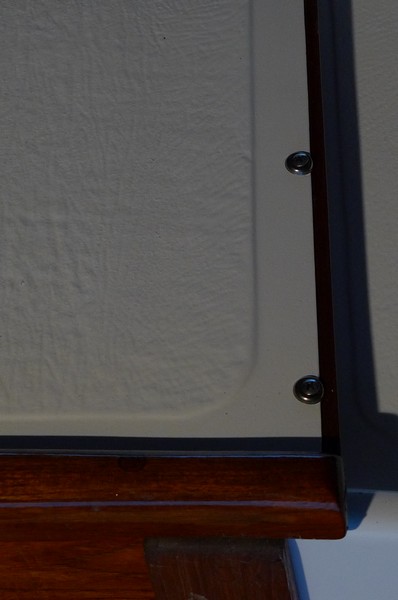
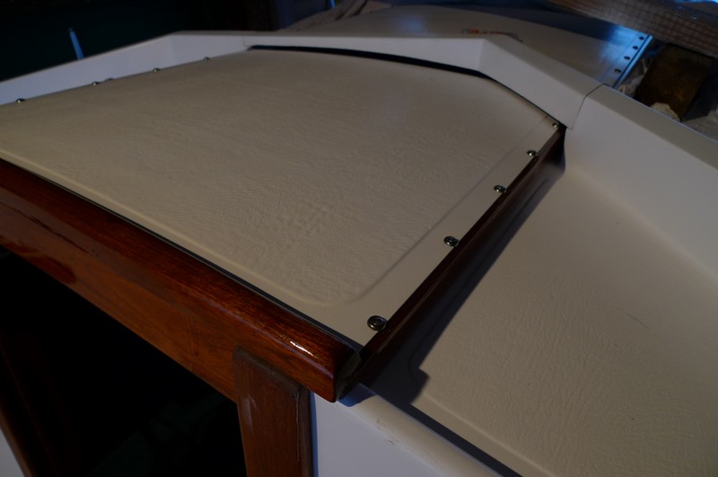
9/21/2010 Deck Hardware Installation I have started installing some more deck hardware. I am using buytl tape and it is easy to work and clean up. Just cut off a piece of tape and stick it to the bottom of the hardware and bolt it down. Then clean up the squeeze out with a plastic puddy knife and your done. Pics below:


9/21/2010 Assembling Aft Cabin I have varnished and installed the two shelves that go in the aft cabin. I have also installed a reading light. I lack another reading light and two fans and the aft cabin will be finished. Pics below:
Hyraulic Steering
I am checking with Vetus Marine on parts availability for the 36 year old Vetus hydraulic steering system on the Rasmus. If parts are impossible to find, I will replace the system. Some have gone with new Edson steering, but at a much greater cost then a new Vetus hydraulic system. So, I will probably replace with new Vetus hydraulic system if I have to go that route. To determine the correct size Vetus system, you have to calculate the maximum torque applied to the specific rudder of the boat, in this case a Hallberg Rassy Rasmus 35. I have carefully measured the rudder perimeter and drawn it in a turbo Cad program, which can give the area of the rudder. The Rasmus rudder has a unique shape that cannot be calculated by the basic length x width equation. The cad program does it for me. Below is the rasmus rudder drawing with Microsoft XL calculations following.
Hallberg Rassy Rasmus Rudder Drawing
Rasmus Rudder Area and Steering Fit
Woodwork: Steering Wheel Pedestal
I purchased a new engine control unit and it would not fit into the original steering wheel pedestal so I built another out of mahogany, teak, and white oak. Pic below:

Reinforcements of white oak mortised into teak base.
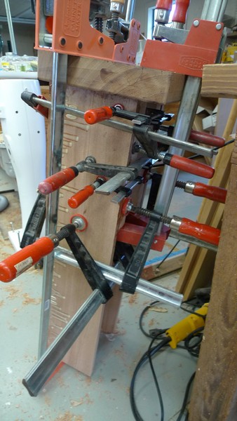
All clamped together
Refrigerator: Finishing the Ice Box and Hooking up Evaporator
I screwed the evaporator in place, ran the coolant lines and hooked them to the compressor, and cut the box lid trim and fitted the lid. I then flipped the breaker and presto, a cold ice box. Pics below:

New ice box lid in mahogany.

Coolant lines in place and tied down with control lines on right. This is just behind the stove position.

Compressor in place and bolted down. It sits just below stove and is vented with fan on the back left. It vents into cabinet under sink. I will leave an opening in the door in front of the compressor, an opening in the cabinet parition between stove and sink, and an opening in door under sink. There is fan in compressor compartment that will draw air in a circular motion through cabinet space to vent compressor heat.

The coolant lines are behind stove and the compressor is under stove. The ice box is to the right of stove.

The ice box nearing completion.

Evaporator in place.

Ice box with lid off.
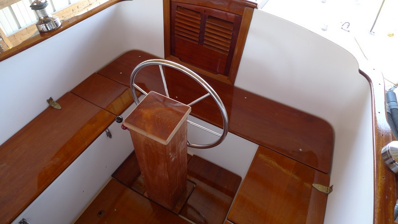
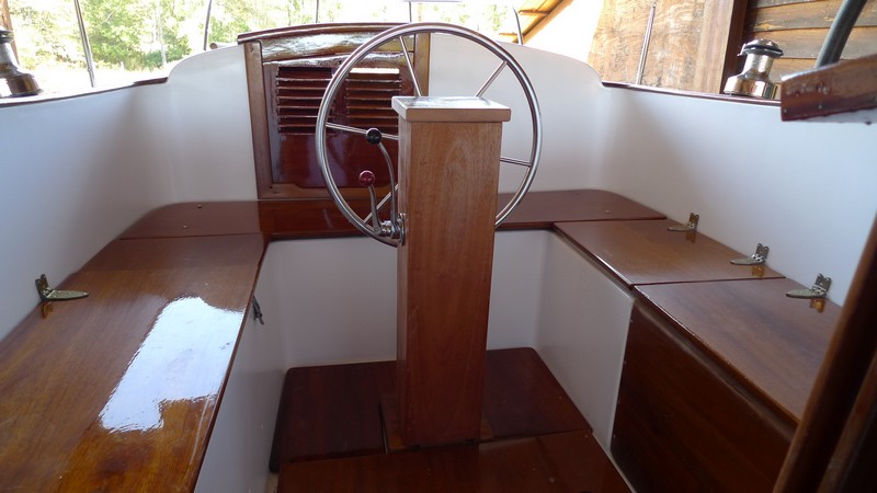
Assembling: Steering Wheel Pedestal
It took all day today to mill and fit the steering wheel pedestal. It is made of teak, African Mahogany, and Cherry. I had to fit the old Vetus hydraulic pump and the new engine controllers in the new pedestal. It took a bit more work than I had planned, but I think the design is good. I made it so if I have to replace the pump, I can do it without tearing apart major parts for the refit. Pics below:
Before
After
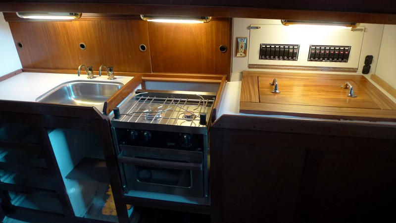
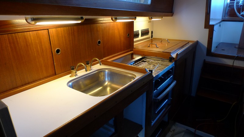
Assembling: Galley
I have finished the refrigerator and it worked first try. Hurray! I have installed the Force 10 stove and installed the uppper cabinet shelves and door. I will probably make a new table top and base early next week. So, at this point I am close to getting the cabin area back together. Pics below:
Before
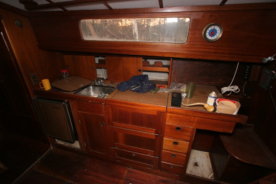
After
Gelcoat and Hull: First Four Coats of Epoxy and Fairing Putty
I spent the weekend working on the epoxy gelcoat. I rolled on 2 coats of pure epoxy with no additive with a 9 inch foam roller. I put it on way too thick. Lack of patience I guess. I would not recommend using a 9 inch roller. I just couldn't control the thickness with it. I worked with System Three general purpose epoxy, using 5 pumps from their mini pump at a time. That was all I could roll on before it set. I then rolled on 2 more coats and added an aluminum powder from West System. I had many pits in the hull from hydrolysis and the epoxy is virtually useless in an unthickened state in filling them. I was told by a West System guy to use a large putty knife and work the epoxy in the pits as it sets. I tried with some success but it was difficult and many pits remained. I did manage to coat the inside of all the pits with epoxy, just couldn't fill them all. I then used System Three Quickfair and used a 6 inch putty knife to trowel the Quickfair on the entire hull with a thin coat. It was not too difficult to get a pretty smooth surface using only the putty knife. It was, however, very hard on the shoulders. I then faired using long boards and then used an 8 inch orbital sander when my shoulders gave out using the long boards. I then rolled on another coat of epoxy with aluminum added using a 4.5 inch roller. I could control the thickness much better with it and got a much thinner and smoother coat. I am slowing down, using only 3 pumps of the epoxy at a time and putting it on much thinner, which I think is the way to do it right. At this point I have 5 coats on and plan to put an additional 2 or 3 more. Pics below:


Pics above are of 4 coats of epoxy and the faired Quickfair Putty.


Pics above are with a coat of epoxy over the faired hull.
Gelcoat and Hull: Starboard Bottom: Day 3 and 4: Coats 6-9.
I have mostly finished the starboard side of the bottom gelcoat repair. I have put on 9 coats of epoxy. It isn't perfect but it is good enough for me. I lack where the boat stands are located. I will brace the boat from the topsides and remove the boatstands for the port side repair. This will save much time. I am improving my technique as I go and will report on the methods that worked best for me when I am finished.
Gelcoat and Hull: Port Bottom: Day 1 and 2
I rolled on 3 coats of pure epoxy and troweled the epoxy into the pits as best I could. I then used a 10 inch sheetrock knife and spread System Three Quickfair over the uncured epoxy. I did this keeping the application as fair as possible. It went on nice and smooth. The next day was spent sanding the fairing putty. This took about 3 or 4 hours. I used good old elbow grease and a long board with 80 grit sandpaper.

Port side faired bottom.

The darker spots are newly applied putty prior to sanding.
Gelcoat and Hull: Port Bottom: Day 3 and 4
I rolled on 1 coat of pure epoxy over the sanded and faired hull. I then added aluminum powder to the epoxy on the next 3 coats. The next day I applied the last 2 coats of epoxy, the last coat being pure epoxy, to make a total of nine coats. And that is that.


Above: Pictures with 7 coats of epoxy applied.
Gelcoat and Hull: 9/21/2010: 9 Coats in 8 Days
I finished the application of the epoxy gelcoat. Let me say that again. I FINISHED THE EPOXY GELCOAT!!!!!!!!!!! And it feels GOOD! It took me 8 days to apply. Once the technique was optimized, it went on pretty good. Here is my:
Final Analysis: I used System Three General Purpose Resin with Fast Hardener. I rolled it on using a 9 inch yellow foam roller cover made for epoxy. I was able to apply 7 pumps of epoxy, using System Three's mini pumps, at a time. I poured the mixed epoxy in a plastic roller pan and loaded the foam roller with a fairly thin uniform coat of epoxy. This is important. If you start with an inconistent covering of epoxy on your roller cover before a application, it will be harder to roll out in uniform thickness. For best results, I worked the roller up, down, sideways, on the hull several times and then finished with a nice vertical stroke to get a nice uniform layer of epoxy. I rolled on the 10.5 ounces of epoxy (7 pumps equals 10.5 ounces) and then went over the freshly rolled surface with a foam paint brush. That is important. It gets the bubbles out and you can knock down any irregularities. Day one: The first two coats is pure epoxy. The third coat I added West System aluminum powder. Then I faired the bottom using System Threes Quickfair. That worked really nice and I spread it with a 10 inch sheet rock knife (stainless steel blade). That combination worked perfect for me. Day 2: I sanded with 80 grit using a long board sander. Coats 4 through 7 I added West Systems aluminum powder added for added water barrier properties. The aluminum powder made it significantly harder to work with and if I had it to do over again I might not use it. It thickened the epoxy and was harder to keep smooth. Day 3: Coat 8 I added aluminum powder and coat 9 was pure epoxy. Important notes: It took most of each morning for the condensation to evaporate from the hull before I started, which was at least to 10:30 A.M. and later. Each coat of epoxy would not increase smoothness of the hull, it would actually decrease smoothness. The more coats, the more "sags" were left in the hull. The epoxy actually magnifies irregularities and sags itself. They were acceptable to me, so I did nothing about it except to use the foam brush after application and smooth out what I could. In order to get a really smooth hull, I would think one would do what I have written above, but after the second to last coat, fair the hull again with Quickfair after the epoxy coat is dry enough and put just one more coat of epoxy on the sanded and faired fairing putty after it dries. I believe this would produce a very smooth surface. The reason you couldn't just do one fairing job before the final coat of epoxy is because the 7 coats of epoxy prior would "magnify" the pits in the hull. It would look like the suface of the moon. You must fair the hull early in the process (but it is recommended to apply two coats of epoxy first, regardless) and then do another late in the process to get a really smooth surface. I was able to work one entire side of the bottom at a time. That surprised me. I thought I would work about 1/3 of each side at a time until finished and then go to the next section. No problems working the entire side at a time. Temps were around 75 to 80 degrees throughout this 8 day period. I had 6 plastic roller pans on hand and used one pan for one coating on one side. I would then get a new roller pan and roller cover for the next coat, and so on. This kept the epoxy from getting gooey. After I had used all six pans, I could pop the epoxy off the first pan to get a nice clean pan for the next coat. I had acetone and rags on hand to clean epoxy from my roller frame after each coat. That kept them usable. Lighting is important to see the epoxy as it is applied. It is clear and very hard to see what you have applied at times. System Three says you have a 72 hour window for applying coats of epoxy on top of each other without sanding. I saw no evidence to the contrary. Everything worked very well. This system worked for me and I am very happy with the results.
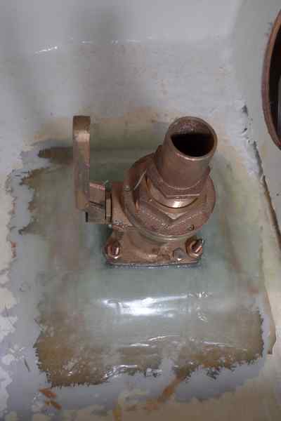
Plumbing: Seacock Installation
I mounted 3/8 inch silicon bronze bolts to 8 inch by 8 inch by 1/2 inch thick G10 block. Then I mounted the seacock onto the block. I then fiberglassed that to the inside of the hull. There was a trick to that because I had to perfectly line up the seacocks to the thru hull and keep it there without slippage until the fiberglassing was done. I did this by slipping the thru hull into its hole and slightly screwing the thru hull to the seacock. I then made a thick epoxy putty with epoxy and wood flour and layered the putty around the hole and under the G10 block. I then pressed the block down onto the putty and let it seat well, squeezing around putty around the edge of the block. I then smoothed out the excess putty and put a layer of fiberglass tape around the perimeter of the block and let it set a bit. Before it cure completely I finished fiberglassing the block in place with 8 to 12 layers of tape. Pics below
.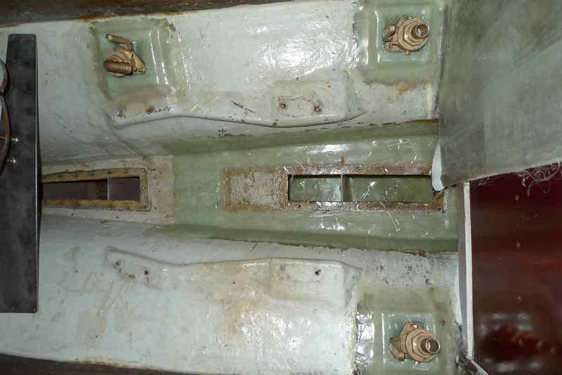
Engine room seacocks installed and fuel tank lid fiberglassed back in place.
Seacock for galley sink installed.
Head bulkhead retabbed.
Head sink seacock installed and bulkhead retabbed.